Sharpes Process Engineering
Process design studies, plant equipment references, safety methodology, and instructional video content.
Sharpes Process Engineering is my independent practice for engineering problems worked past any single plant. This portfolio is what that looks like — full process design studies worked from first principles, equipment and safety references built to be actually used, and sixty-plus instructional videos on thermodynamics and process design worked through at the board.
Equipment Design, Process Safety & Engineering History
25 original presentations organized by topic. Each deck links to an interactive viewer.
› Equipment Design & Heuristics 15 presentations
Six absorber types: agitated vessels (batch/continuous), bubble-cap towers (high residence time, low liquid rates), cooler absorbers (external/internal cooling for high heat of absorption), spray towers (droplet contact, entrainment tradeoffs), packed towers (most common, countercurrent gravity drainage), and venturi scrubbers (single-stage, high-solubility gases only).
Open Presentation ▶ Watch Video36-slide design and evaluation guide — trayed vs packed selection (flow parameter Fp thresholds), structured vs random packing rules (tower diameter, liquid rate, pressure drop), packing factor Fp, flood point correlations (Sherwood-type), minimum/maximum liquid wetting rates, liquid distributor types and drip-point density, redistributor spacing, support plate weight limits, and three design methods: Kremser (lean gas), Edmister (multi-component), and HTU/NTU with mass transfer coefficient correlations.
Open PresentationCompression basics (pressure ratio vs capacity tradeoff, heat capacity ratio k, polytropic efficiency). Four types: centrifugal (backward-curved impellers, surge at min flow, choke at max flow), reciprocating (high pressure ratio, interstage cooling), rotary (screw, lobe, sliding vane, liquid piston), and axial (low head, high flow, gas turbines). Vacuum service and driver selection.
Open Presentation ▶ Watch VideoCompressor train sizing: pressure ratio and capacity tradeoffs across stages, interstage cooling placement, and polytropic vs isentropic efficiency calculations for driver power sizing.
Open Presentation ▶ Watch VideoFilm vs dropwise condensation mechanisms and heat transfer coefficient differences. Condensation complications from non-condensable vapor accumulation. Design heuristics for contact condensers (equilibrium temperature basis), dilute isothermal service, and temperature-range service. Source: Chemical Engineers' Condensed Encyclopedia of Process Equipment.
Open Presentation ▶ Watch VideoNatural draft (hyperbolic tower, chimney effect, density differential), mechanical draft (induced vs forced fan, crossflow vs counterflow), atmospheric spray, and specialty types (deck-filled, coil-shed). Operating terminology: wet-bulb temperature, cycles of concentration, drift, blowdown, makeup water calculations, plume formation, and acceptance testing. Source: Encyclopedia of Process Equipment.
Open Presentation ▶ Watch VideoNine flow meter types: Venturi, Dall (lower permanent pressure drop), orifice plate (sharp-edge contraction, straight-run requirements), flow nozzle (high Reynolds number), pitot tube, positive displacement (piston meters, batch/blending), mechanical (rotameters), magnetic (Faraday's law, conductive fluids), and ultrasonic/Doppler (suspended solids service). Comparison table and selection criteria.
Open Presentation ▶ Watch VideoThree distinct analysis workflows — Design (sizing new equipment from heat duty and temperature requirements to meet performance targets), Rating (predicting actual duty and pressure drop for existing equipment at off-design operating conditions), and Simulation (what-if studies, fouling buildup, startup/shutdown transients, sensitivity analysis across process changes).
Open Presentation ▶ Watch VideoTemperature crossover management: single 1-1 pass (TC-proof but velocity-limited), multi-pass shell/tube configurations, and the conditions under which each approach applies. Shell-side vs tube-side fluid assignment rules: corrosive fluids in tubes (easier bundle replacement), dirty fluids in tubes (easier cleaning), condensing fluids in shell, high-pressure service in tubes (thinner vessel walls).
Open PresentationFouling mechanisms from Bott's Fouling of Heat Exchangers: particulate, crystallization/scaling (supersaturation, nucleation, normal vs. inverse solubility), corrosion, and chemical-reaction fouling, each with where it deposits, upstream prevention, and in-exchanger mitigation. Type-independent best practice (clean upstream service, separation ahead of the exchanger), deposit-growth trends (asymptotic, linear, falling-rate), and the Kern-Seaton asymptotic model Rf(t) = Rf*(1 − e−t/τ).
Open PresentationCorrosion from Perry's 9th Edition: electrochemistry, Pourbaix passivation diagrams, and polarization; localized corrosion (pitting, crevice, intergranular, galvanic, dealloying); environmentally assisted cracking (SCC, hydrogen embrittlement, liquid-metal embrittlement, corrosion fatigue); high-temperature gaseous corrosion (oxidation, carburization, sulfidation, halogens, nitridation, molten salts); and prevention practice for heat exchangers, towers, tanks, and piping, plus process-environment changes (passivation promotion, deaeration, scale enhancers).
Open PresentationFixed-roof tanks (flat, conical, dome roof types), floating-roof tanks (pontoon buoyancy design, rim seals for low-boiling liquids, solar boiling prevention), conservation gas holders (variable volume at fixed pressure), and open-top tanks. Tank appliances: conservation vents, hatches, mixers, and their leak exposure. Source: Encyclopedia of Process Equipment.
Open Presentation ▶ Watch VideoSouders-Brown K factor (0.15–0.25 ft/s, decreasing at higher pressure) for vessel diameter sizing, height heuristic (H = 4×D baseline), liquid residence time by service (1–3 min clean hydrocarbon, 3–5 min moderate viscosity, 5–10 min dirty/foaming), mist extractor knockdown of entrained liquid, nozzle placement, and independent PIC (vapor)/LIC (liquid) control loops — must not be coupled to avoid interaction.
Open Presentation ▶ Watch VideoCross-equipment heuristics for fast first-pass checks: control valve authority (50–60% of system pressure drop for adequate control), PSV relief scenario selection under API 521 (including high-pressure-into-low-pressure breakthrough evaluation), pump best-efficiency-point tradeoffs (65–95% BEP range, reliability vs. energy consumption), and heat exchanger simulation methods (Dittus-Boelter, Bell-Delaware).
Open PresentationDecision workflow for selecting a thermodynamic property method — Classical (gamma-phi), EOS (phi-phi), or Hybrid — gated on electrolyte presence, liquid-phase ideality (UNIFAC, Kamlet-Taft/Gutmann DN-AN, and Flory-Huggins fallbacks), and pressure vs ~10 bar. Stress-tested and validated against 11 real petrochemical process families from the Meyers Handbook, with per-bucket case-study results and characterization of which systems typically land in each approach.
Open Presentation› Process Safety 9 presentations
From GFEDPS Chapter 7 — protection layer hierarchy (ISD → control → active mitigation), electrical area classification (ANSI/NFPA 70 Class I/II/III), SIS/SIL/IPL definitions (IEC 61511), pressure relieving systems, equipment isolation and blowdown, flare systems (API 521), vapor incineration (40 CFR), fire protection modes (HC burning, pyrophoric material), deflagration/detonation arresters, explosion suppression, and dike containment design.
Open Presentation ▶ Watch VideoSafeguarding hierarchy (passive → active, decreasing reliability with increasing complexity). ISD strategies applied unit-by-unit: tank reactors (runaway prevention), continuous reactors, mass transfer columns, heat exchangers (tube leak prevention: thermal difference reduction, heat throttle), dryers (combustible dust, multicomponent LEL reduction), pumps (deadheading, cavitation), compressors, fired equipment, piping (40% of LOC incidents, ASME B.31), and utilities.
Open Presentation ▶ Watch Video27-slide study guide from Crawley & Tyler's Guide to Best Practice — ICI origins and 6-stage Hazard Study workflow, guideword/parameter matrix construction, node definition, cause-consequence-safeguard chain evaluation, risk matrix (qualitative), HAZOP team assembly (leader, scribe, discipline members), meeting structure, recording format (dedicated PHA software, sectioned tables), auditing, and training pathways. Handoff to LOPA and MOC covered.
Open PresentationAPI 521 overpressure scenario identification (closed outlets, cooling/reflux failure, volatile material ingress, overfilling, control failure, fires, tube rupture, utility failure, hydraulic expansion, chemical reactions per DIERS methodology) → governing scenario selection. Vacuum relief evaluation, vapor depressuring design (vessel rupture pressure, failure time, brittle failure temperature), and operator response time thresholds.
Open Presentation ▶ Watch VideoFrom GFEDPS Chapter 8 — three PSI categories under OSHA PSM: Chemical Hazards (MSDS, reactivity, toxicity, explosive limits, heat of combustion), Process Technology (C&E matrix, P&IDs, SIS lifecycle documentation, PHA findings), and Process Equipment (equipment specs, drawings, electrical diagrams, structural analysis). Distinction between design basis, engineering design package, and EDMS-managed equipment files.
Open Presentation ▶ Watch VideoFour-step Apollo RCA — Step 1: Problem definition (what/when/significance/impact), Step 2: Reality chart construction (causal chains with action and condition causes; three evidence types: sensed, inferred, testimonial), Step 3: Effective solutions (criteria: prevent recurrence, within control, meets organizational goals; creative thinking methods), Step 4: Implement and track with profitability review to inform future decisions.
Open Presentation ▶ Watch Video26 incident case studies from Kletz's "What Went Wrong" — compressed air oil deposits, aluminum dust explosion (Huntington IN 2003), furnace tube rupture, amine tower BLEVE (17 dead), Longford explosion (Exxon Australia 1998), Feyzin tank BLEVE (TotalEnergies 1966), nitrogen asphyxiation (Union Carbide 1998), HF Puget Sound spill, floating roof tank fire (Wales 1983), water hammer rupture (BP UK 2000), static electricity in powder, check valve backflow, and others with root cause lessons.
Open Presentation ▶ Watch VideoChapter-by-chapter walkthrough of CCPS Guidelines for Hazard Evaluation Procedures (76 slides): incident anatomy and safeguard purpose; study preparation (scope, team, scheduling); hazard identification (inherent hazards, interaction matrices, worst-case consequence); non-scenario methods (PreHA, Safety Review, Relative Ranking, Checklist); scenario methods (What-If, What-If/Checklist, HAZOP, FMEA, Fault Tree with minimum cut sets, Event Tree, Cause-Consequence); the Chapter 6 selection flowchart and MOC hazard reviews; risk-based safeguard adequacy through LOPA; follow-up and action-item resolution; and special applications (procedures, programmable systems, reactivity, human factors, facility siting).
Open Presentation ▶ Watch VideoLOPA methodology as a semi-quantitative follow-on to HAZOP — initiating event frequency estimation, independent protection layer (IPL) identification and credit rules, enabling conditions and conditional modifiers, and comparison of mitigated event likelihood against corporate risk criteria to determine required SIL.
Open Presentation› Engineering History 1 presentation
Profiles of fifty-nine engineers and scientists behind the methods process engineers use daily: Henry Kister (distillation, Fluor), Ernest Ludwig (Applied Process Design), Alois Kremser and Wayne Edmister (absorption), Max Peters and Ronald West (Plant Design and Economics), Donald Kern (process heat transfer), Igor Karassik (Pump Handbook), Joseph Leung (relief sizing), Thomas Bott and James Knudsen (fouling), Jürgen Gmehling (UNIFAC), Merrel Fenske, A.J.V. Underwood, Mott Souders, Sabri Ergun, Allan Colburn, Thomas Chilton, Lawrence Evans (Aspen Technology), and more, from Bernoulli and Stokes to present-day Perry's section editors.
Open PresentationInteractive Calculations
Live calculators built from API standards and first principles. Adjust any slider and results update instantly.
› API 521 §5.5.10 — HEM Tailpipe Backpressure Calculator Method & code USC units
Homogeneous equilibrium model (Leung 1986) · USC units · Solves for upstream pressure p₁ · Built-up backpressure check per API 521 7th Ed.
API 521 7th Ed. (Jun 2020) §5.5.10 · Homogeneous equilibrium model (Leung 1986) · USC units · For engineering study use only
› Centrifugal Pump Sizing — Case Study Tool Method & code USC/SI toggle
Centrifugal Pump Sizing — Case Study Tool
thermo table (11 pure compounds) embedded in this file — fully self-contained, no backend, drops straight into a static site. Every slider is bounded per sizing_tool_parameter_limits.md; less-frequently-changed constants are fixed in code rather than exposed here.Fluid
Duty conditions
Vendor documents
Screening — single-stage centrifugal (radial/mixed-flow) range
Speed, NPSH & cavitation
| Poles | N (rpm) | Nss | Status |
|---|
Impeller & collector geometry
Predicted performance curve — trim-diameter family
Axial thrust & balancing
Final balanced performance
First-pass numbers (pre-balancing) — reference only
Assumptions used & known gaps
Fixed internal constants (see sizing_tool_parameter_limits.md)
Not implemented (deck doesn't yet give a closed form) — case-study findings
› Flow Meter Selector — Process Conditions → Recommended Meter Type Method & code 10 meter types
Rule-based selection guide built from the criteria in the Flow Meters presentation — every recommendation below cites the specific slide fact behind it, not a generic scoring model. Set your process conditions; the meter list re-ranks live.
Selection logic derived from Flow Meters presentation content (Venturi, Dall, orifice plate, flow nozzle, Pitot tube, positive displacement, rotameter, turbine, magnetic, ultrasonic/Doppler) · For engineering study use only
› Compressor Train Sizing Calculator — Type, Efficiency, Power & Stage-Count Optimizer Method & code N = 1-6 stages
Sizes a multi-stage compressor train (equal pressure ratio per stage, full intercooling back to suction temperature) from Compressor Selection/Sizing methodology — auto-suggests type and efficiency method from your process conditions, then sweeps N = 1-6 stages to recommend the economically optimal stage count (Seider Ch. 16.5 equipment costing + Peters & Timmerhaus payback screen). Change any input and every result recomputes live. See the Compressor Selection, Compressor Train Sizing, and Perry's Compressors presentations for the underlying method.
Show N = 1-6 stage-count sweep (Stage-Count Optimizer detail)
| N | r_stage | H_ad (ft) | Type | Tout (°F) | Tallow flag | Train hp | TCI ($) | Incr. PBP (yr) | Passes? |
|---|
Known simplifications / gaps (carried from the source workbook)
- Fig. 10-64 type-selection boundaries are eyeballed from a chart image, not precisely digitized — cross-check borderline operating points against the reference chart.
- Gas library MW/k are approximate ideal-gas values near ambient — use Custom/Manual Entry for mixtures or non-ideal conditions.
- Scale-Up method needs external Casey & Robinson friction-factor data not present in this project's source decks.
- Balje method's chart itself isn't available — ηc must come from an external chart reading.
- Seider Ch. 16.5 only gives compressor cost equations for Centrifugal, Reciprocating, Screw — every other type shows "n/a - outside Seider correlation coverage," not a fabricated fit.
- CEPCI defaults to 567 (no escalation) unless you pick a real year.
- Combined tax rate defaults to 21% flat federal (no state) — editable above.
- Depreciation life for the after-tax cash flow reuses the evaluation period N, not a separately specified MACRS schedule.
- The Stage-Count Optimizer holds ηp constant across the N=1-6 sweep — a documented Class-5 (±30-50%) screening simplification, not per-row-accurate.
- Intercooler sizing uses an assumed overall U and a standard 90/120°F cooling-water basis to back into an area for costing — not a full thermal/mechanical HX design.
Equal pressure ratio/stage, full intercool to T1 · Seider, Seader, Lewin & Widagdo Ch. 16.5 equipment costing · Peters & Timmerhaus Eq. 8-2a/8-2c payback screen · For engineering study use only
› Jacketed / Packed-Bed Reactor Scale-Up Calculator Method & code lab → pilot
Scales a jacketed or packed-bed PFR exothermic reaction from lab to pilot diameter, holding target conversion and L/D fixed while sweeping tube diameter D. Every reaction has its own binding scale-up constraint — cooling surface/volume, thermal stability, or pressure drop — derived from first principles and verified public literature (see reference panel), not vendor/proprietary numbers. Pick a reaction and L/D; every result and chart recomputes instantly from a precomputed sweep (Python/SciPy, baked in at build time — no live solver in the browser).
Why this diameter — the limits behind the recommendation
Known simplifications / gaps
› EO Runaway Relief Calculator — Loss of Mixing (EG → PEG) Method & code preliminary
KOH-catalyzed ethoxylation of ethylene glycol to PEG · local EO pocket at the feed point · tempered venting at relieving pressure · API 520 / Leung ω sizing · SI units, pressures bar absolute · preliminary — see basis and limitations below
Full scenario description
Advanced assumptions
› Pressure Vessel Cost vs. Diameter — ASME VIII-1 Wall, MAWP/MAWT, Material Screen, Itemized Installation Method & code FEL-1
Sizes a pressure vessel's wall from ASME Section VIII-1 (UG-27, allowable stress from ASME II-D 2013), back-calculates MAWP and MAWT, screens materials of construction for the service (corrosion allowance vs. cracking mechanisms), and builds purchase + itemized installation cost (Seider Ch. 16, Guthrie line items) across a diameter sweep. A second tab applies the same engine to the Haber-Bosch synthesis-loop pressure trade-off: equilibrium conversion and recycle vs. converter/separator wall and compression.
Inputs
Geometry
Process conditions
Material of construction
Installed cost vs. diameter
Material comparison vs. diameter
Mechanical design at D =
Cost build-up (itemized installation)
Material screen at this diameter
Loop basis
Compressor drive & energy
Annualized cost vs. loop pressure
Loop response vs. pressure
Pressure sweep table
Calculation chain
- Design conditions (Seider §16.5): Pd = 10 psig if Po ≤ 5 psig; exp{0.60608 + 0.91615 ln Po + 0.0015655 (ln Po)²} for 5–1000 psig; 1.1·Po above 1000 psig. Td = To + 50 °F.
- Allowable stress S(Td): ASME II-D 2013 Table 1A/1B, Section VIII-1 column, linear interpolation. Local file
asme_iid_stress.json(page refs per material). Blank above the material's VIII-1 temperature limit. - Pressure thickness: UG-27 tp = PdR/(SE − 0.6Pd) (= Seider 16.60); Appendix 1-2 thick-wall form t = R(eP/SE − 1) when P > 0.385SE. E = 0.85 (spot RT) up to 1.25 in, 1.0 above (Seider).
- Vertical wind/seismic (Seider 16.62): tw = 0.22(Do+18)L²/(S Do²); tv = tp + tw/2 (average of top and bottom).
- Minimum thickness (Seider): ¼ in to 4 ft, 5/16 to 6 ft, 3/8 to 8 ft, 7/16 to 10 ft, ½ in to 12 ft; +1/16 in per 2 ft above 12 ft (extrapolated).
- Corrosion allowance = rate × design life (min 1/16 in). Credit toggle: off → t = max(tp, tmin) + CA (Seider); on → t = max(tp + CA, tmin) (Coulson, minimum includes CA). Round up to plate: 1/16 in steps to ½ in, 1/8 in to 2 in, ¼ in above.
- MAWP: UG-27 inverted on the corroded thickness (tnom − CA) at Td. MAWT: highest temperature at which S(T) still gives MAWP ≥ Pd on the corroded wall, capped at the VIII-1 limit. Corrosion life = (tnom − tp)/rate: all metal above the pressure requirement, including min-thickness and plate-rounding surplus.
- Weight (Seider 16.59): W = π(Di+t)(L+0.8Di)t·ρ with ρ = 0.284 lb/in³ (Seider's cost basis; heads same thickness as shell). Actual shipping mass uses the material's own density.
- Purchase cost (Seider 16.52–16.56, CE 567): CP = FMCV + CPL. Vertical CV = exp{7.1390 + 0.18255 lnW + 0.02297(lnW)²}, CPL = 410D0.7396L0.70684; horizontal CV = exp{5.6336 + 0.4599 lnW + 0.00582(lnW)²}, CPL = 2275D0.2094. FM from Seider Table 16.26.
- Installation, itemized: Guthrie line items (Seider Table 16.10: piping 0.456, concrete 0.051, steel 0.031, instruments 0.102, electrical 0.020, insulation 0.049, paint 0.005, erection 0.554, setting 0.076, freight 0.080, overhead 0.571, engineering 0.296 × CP; sum 2.291) scaled so they total the vessel bare-module factor FBM − 1 (Seider Table 16.11: vertical 4.16, horizontal 3.05). Installation is charged on the carbon-steel purchase cost (Seider Eq. 16.12). Assumption: vessel line items share the heat-exchanger split.
- Contingency + fee: 15% + 3% (Seider, on direct permanent investment ≈ bare-module cost for one item).
- Cost year: escalated CE 567 → 800 (single fixed index; relative comparisons are the point of this tool).
Service screening
Follows the Plant Resources\Materials of Construction methodology (per-mechanism, UNS-named, Perry's 9th Table 25-3 ratings, FEL-1 screening only). Corrosion rates are illustrative placeholders pending a sourced corrosion database (NACE/MTI data are not on disk). Hot-hydrogen limits are an approximate reading of API 941 Nelson curves at high H₂ partial pressure. Verify before use.
Haber-Bosch case study
Equilibrium: Gillespie-Beattie Kp (atm⁻¹, ½N₂ + 3/2H₂ ⇌ NH₃), ideal gas (fugacity corrections neglected, which understates conversion at high P), 3:1 H₂:N₂ plus inerts. Per-pass outlet NH₃ = inlet + approach × (equilibrium − inlet). Inlet NH₃ = NH₃ vapour pressure at the separator T ÷ loop P. Loop flow F = ξ(1+yout)/(yout − yin). Converter catalyst volume = converter inlet flow at STP ÷ GHSV (standard-condition space velocity, as industrial converters are rated); vessel volume = 1.3 × catalyst. Because the catalyst volume does not shrink with pressure, wall metal (∝ P × V) and converter capital rise with loop pressure. A residence time at actual conditions would make V ∝ 1/P and cancel that effect exactly (pV = nRT). Separator: Souders-Brown K = 0.107 m/s (Ammonia Process knock-out basis), L/D 3.5. Makeup compressor: intercooled (40 °C), equal ratios ≤ 3 per stage, ideal-gas polytropic; circulator lifts loop flow by the loop ΔP. Compressor cost: Seider Eq. 16.36 centrifugal CB = exp{9.1553 + 0.63 ln PC} (hp, CE 567, includes motor) × FD (1.15 for a steam-turbine drive, Eq. 16.35), installed ×2.15. Compression energy: electric drive = grid price ÷ 0.95 motor efficiency; steam-turbine drive = steam rate × blended steam value, where the blend is the share of turbine steam raised from recovered reformer convection-section / loop WHB heat (default $0.53/t, its boiler-feed-water cost, i.e. surplus heat with no other use) vs make-up steam that must be fired or bought (default $17.60/t, Seider Table 17.1, 450 psig). Default steam rate 3.45 kg/kWh: condensing turbine, 105 bar / 510 °C (Ammonia Process Memoir HP header) to 0.10 bar, 80% isentropic (IAPWS-95); a back-pressure turbine to 4.5 bar needs ≈ 5.9 kg/kWh. Integration only pays when the steam is genuinely surplus: if it could otherwise run a turbo-generator, its value approaches the grid price and the steam drive saves little. The recovered-steam supply is not capped (no plant steam balance). Refrigeration duty is not included. Proof of concept: trends, not a design.
Sources on disk
- ASME II-D 2013 (Customary): Vessel Scale Up folder.
- Seider, Seader, Lewin & Widagdo, Ch. 16: FEL Projects\Economics\Seider.pdf (PDF p.476–477, 500–503).
- Coulson & Richardson Vol. 6 (Sinnott) §13.4.8: Textbooks (Level 1)\Process & Plant Design.
- Meyers, Handbook for Petrochemical Production Processes: Textbooks (Level 1)\Process-Specific References. Preset conditions per chapter noted in the preset hint.
Full Process Design Studies
Two plant-scale design projects worked from first principles — mass and energy balances, equipment sizing, thermodynamic calculations, and process narrative written as a working engineering memoir.
Complete design study of an SMR-based ammonia synthesis loop. Covers the primary reformer (tube-side kinetics, heat flux limits), high- and low-temperature WGS reactors, CO₂ removal, methanation, and the Haber-Bosch synthesis loop with compression train. Full molar flow balances and equipment sizing at each stage.
View DocumentDesign study of a spent sulphuric acid regeneration unit. Covers the combustion furnace (air/acid feed ratios, flame temperature), catalytic SO₂→SO₃ converter with interbed cooling, oleum and final absorbers, and the waste heat recovery train. Equipment sizing and operating rationale at each section.
View DocumentNotes & Problem Sets
Raw chapter notes from Perry's and worked problem sets from LearnChemE and YouTube lecture series.
› Perry's Reference Notes 7 notes
› Problem Sets 5 sets
Primary References
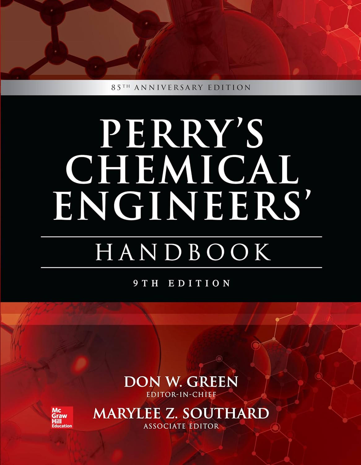
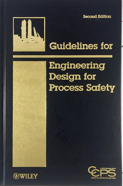
› Technical Library 13 books
Thermodynamics & Process Design — Worked Problems
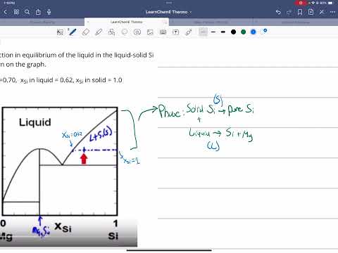
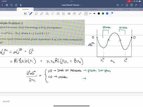
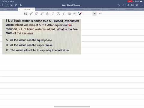
72 hand-worked problems recorded as instructional walkthroughs, organized by playlist. Click any thumbnail to play.
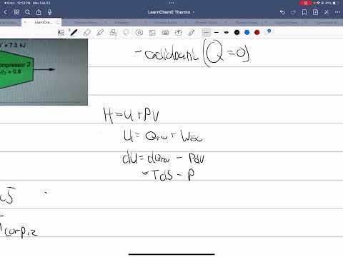
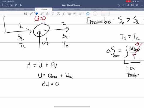
› Thermodynamics — Worked Problems 52 videos










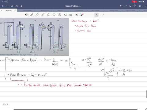
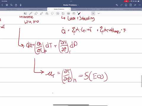
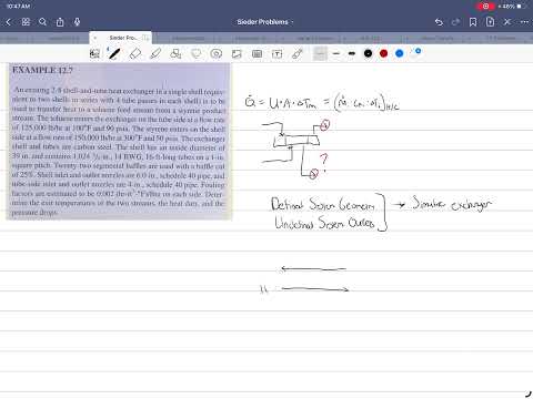
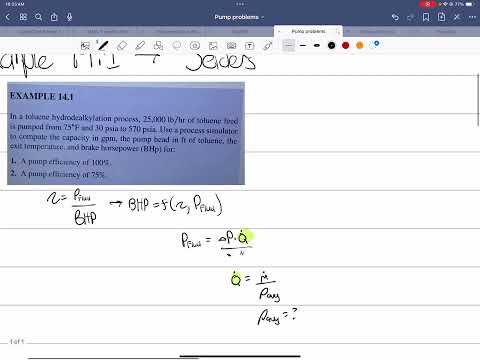
› Process Design — Seader Textbook 9 videos





› Design Problems — Peters Textbook 11 videos